


Views: 0 Author: Site Editor Publish Time: 2026-05-20 Origin: Site


A pin insulator is a device used in power distribution systems to support and insulate electrical conductors, typically operating at voltages up to 33kV. It consists of a non-conductive material like porcelain or polymer shaped like a bell, which is secured to a supporting structure using a metal pin. The primary working principle involves providing a high-resistance path to prevent current flow while withstanding mechanical stress and environmental factors.
Understanding the nuances of these insulators is essential for engineers and procurement specialists looking to optimize grid performance. In this comprehensive guide, we will explore the internal mechanisms, selection criteria, installation methods, and maintenance protocols for pin insulators. We will also delve into the specific challenges faced during their lifecycle and the diverse industrial applications they serve.
Selection Process of Pin Insulator
Installation Process for Pin Insulator
Application Areas of Pin Insulators
Maintenance Practices for Pin Insulators
Challenges and Issues Facing Use of Pin Insulators
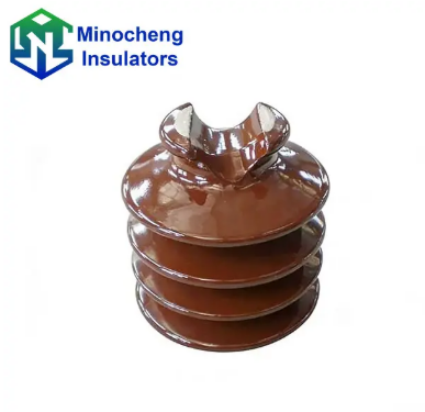
The selection process of a pin insulator involves evaluating specific electrical and mechanical parameters, such as the maximum operating voltage, mechanical load capacity, and the environmental conditions of the installation site to ensure system stability.
When choosing a Pin Insulator, the first and most critical factor is the voltage rating. Typically, pin insulators are limited to applications up to 33kV because, beyond this level, the size and weight required for sufficient insulation become economically and physically impractical. Engineers must calculate the peak voltage the system might experience, including potential surges, to ensure the dielectric strength of the porcelain or composite material is sufficient to prevent puncture.
Another vital consideration is the creepage distance, which is the shortest path along the surface of the insulator between the energized conductor and the grounded pin. In areas with high humidity, salt spray, or industrial pollution, a longer creepage distance is required to prevent "tracking" or surface leakage. Selecting a design with multiple "petticoats" or "sheds" helps increase this distance and keeps the underside of the insulator dry during rain, maintaining high resistance even in inclement weather.
Mechanical strength is the third pillar of the selection process. The insulator must support the weight of the conductor and withstand external forces like wind pressure and ice loading. The cantilever strength of the pin itself must be matched to the tension of the line. Before finalizing a purchase, it is essential to verify that the product meets international standards like IEC or ANSI, ensuring that the high-quality insulation components you integrate into your project are rigorously tested for both dry and wet flashover voltages.
Voltage Threshold: Matching the insulator to the line voltage (usually 11kV, 22kV, or 33kV).
Material Type: Deciding between traditional glazed porcelain or modern lightweight silicone rubber/polymers.
Environmental Adaptation: Choosing specific shed profiles based on the pollution levels of the geographic region.
The installation process for a pin insulator requires securely fixing the insulator to a steel or wooden cross-arm using a galvanized pin and then binding the conductor into the top groove of the insulator using specialized tie wires.
Preparation is the first stage of a successful installation. The cross-arm on the utility pole must be pre-drilled to accommodate the shank of the insulator pin. The pin is inserted through the hole and tightened with a heavy-duty washer and nut. It is crucial that the pin is perfectly vertical and stable, as any tilt can lead to uneven mechanical stress on the porcelain body, potentially leading to cracks over time.
Once the pin is set, the Pin Insulator is screwed onto the threaded head of the pin. Most pins use a lead or nylon thread to provide a snug fit that allows for slight thermal expansion without fracturing the brittle porcelain. The insulator should be tightened by hand until it is firm against the shoulder of the pin. Over-tightening with tools should be avoided as it can cause internal stress in the material.
The final step involves the conductor attachment. The electrical wire is placed in the groove at the top of the insulator. To secure it, a "tie wire" made of the same material as the conductor (usually aluminum or copper) is wrapped around both the conductor and the neck of the insulator. This binding must be tight enough to prevent the wire from slipping but flexible enough to allow for minor vibrations caused by the wind. Proper binding ensures that the weight of the cable is evenly distributed across the head of the insulator.
Hardware Inspection: Checking the galvanized pin for thread integrity and rust.
Mounting: Securing the pin to the cross-arm and the insulator to the pin.
Stringing and Binding: Placing the conductor in the groove and applying the correct tie-wire pattern.
Pin insulators are primarily applied in overhead distribution lines for rural and urban power grids, substations, and industrial complexes where the operating voltage does not exceed 33kV.
In the realm of power distribution, these insulators are the workhorse of the 11kV and 15kV networks. Because they are cost-effective and easy to install, they are the preferred choice for distributing power from local substations to residential and commercial transformers. Their rigid mounting makes them ideal for straight-line runs where the conductor is not subjected to extreme tension or sharp angles.
Substations also utilize pin insulators for supporting busbars and other internal wiring. In these environments, the insulators provide a compact solution for maintaining safe clearances between energized components and the grounded support structures. They are often used in combination with other types of insulators to create a robust and redundant protection system against electrical faults.
Furthermore, specific industrial sectors, such as mining and heavy manufacturing, rely on pin insulators for their localized power grids. For instance, in a large factory complex or a remote mining site, these insulators support the lines that feed heavy machinery. When sourcing components for such demanding environments, selecting ANSI standard insulators ensures that the hardware can withstand the vibrations and potential chemical exposure often found in industrial settings.
Rural Electrification: Long-distance distribution where cost-efficiency is a priority.
Urban Low-Voltage Grids: Providing power to street lights and residential neighborhoods.
Temporary Power Setups: Use in construction sites or temporary event power lines due to their ease of assembly.
Maintenance practices for pin insulators focus on periodic visual inspections, cleaning of the surface sheds to remove contaminants, and using thermal imaging to detect hotspots that indicate internal failure.
Surface contamination is the primary enemy of an insulator's performance. Over time, dust, salt, and industrial soot accumulate on the porcelain sheds. When these layers become moist due to fog or light rain, they become conductive, leading to leakage currents and potential flashovers. Regular cleaning, often performed with high-pressure water jets (live-line washing) or manual wiping during scheduled outages, is essential to restore the original dielectric properties of the unit.
Visual inspections are conducted to identify physical damage such as "glaze chipping" or deep cracks. Even a small crack can allow moisture to penetrate the porcelain body, leading to a "puncture" where the arc travels through the material rather than over the surface. Inspectors also look for signs of "tracking"—black carbonized paths on the surface—which indicate that the insulator is nearing the end of its functional life and needs immediate replacement to prevent a line fault.
Advanced maintenance involves the use of infrared thermography. By scanning the insulators with a thermal camera, technicians can identify temperature anomalies. A healthy insulator should be at the ambient temperature; if it appears significantly hotter, it usually indicates internal leakage current or a failing pin connection. This proactive approach allows utilities to replace faulty units before they cause a widespread blackout, ensuring the power distribution network remains stable and safe for the public.
Visual Audit: Checking for cracks, chips, and rust on the metal pin.
Cleaning Cycle: Removing deposits based on local environmental severity.
Electrical Testing: Periodic resistance testing to ensure insulation integrity remains above safety thresholds.
The challenges facing the use of pin insulators include their limited voltage capacity, susceptibility to mechanical failure under extreme tension, and the risk of puncture caused by high-voltage surges.
One of the most significant limitations of the pin insulator is its economic ceiling at 33kV. As the voltage increases, the thickness of the porcelain required to prevent a puncture becomes exponentially larger. This results in a heavy and bulky insulator that puts immense strain on the cross-arm and pole. For voltages higher than 33kV, suspension insulators are almost always used instead, as they provide better flexibility and scalability.
Another issue is the risk of "Puncture vs. Flashover." A flashover occurs when the air around the insulator breaks down and an arc jumps across the surface; this is usually non-destructive. However, a puncture occurs when the arc blasts through the porcelain itself. Once a pin insulator is punctured, it is permanently damaged and must be replaced. Designing an insulator where the "flashover distance" is significantly shorter than the "puncture distance" is a complex engineering challenge that requires high-purity materials and precise manufacturing.
Environmental degradation also poses a continuous threat. In coastal areas, salt accumulation can lead to frequent arcing, which erodes the protective glaze of the porcelain. Similarly, in freezing climates, ice buildup can bridge the gaps between the sheds, effectively shortening the creepage distance and causing a fault. Choosing reinforced polymer or specialized porcelain designs can mitigate some of these issues, but environmental monitoring remains a necessity for any utility operator.
| Issue | Description | Impact |
| Voltage Ceiling | Impractical size for applications above 33kV. | Limits use to distribution levels. |
| Puncture Risk | Internal failure due to surge or material defect. | Permanent damage and power outage. |
| Mechanical Stress | Brittle nature of porcelain under bending loads. | Risk of snapping during storms or high winds. |
The pin insulator remains a fundamental component of modern electrical distribution. By offering a balance between cost, ease of installation, and reliable performance, it supports the infrastructure that powers our daily lives. From the selection of high-grade materials to the implementation of rigorous maintenance schedules, every step in the lifecycle of a pin insulator is vital for grid resilience.
As technology evolves, we see the integration of composite materials and smarter monitoring techniques, yet the core principles of the pin insulator remain unchanged. Whether you are upgrading a local grid or designing a new industrial facility, choosing the right insulation solution is the first step toward a safe and efficient electrical future. For those seeking durable and tested components, investing in high-quality hardware is the best way to ensure long-term success and minimal downtime.


