


Views: 0 Author: Site Editor Publish Time: 2026-05-10 Origin: Site


A pin insulator is a specialized device used in power distribution to isolate electrical wires from physical supports like utility poles or cross-arms. It consists of a non-conductive body, typically made of porcelain or polymer, which is mounted on a metal pin. This design ensures that electricity remains within the conductor and does not ground through the pole, even under high-voltage conditions or adverse weather.
In the following comprehensive guide, we will delve deep into the technical specifications, structural design, and operational benefits of pin insulators. From the selection of high-grade raw materials to the rigorous maintenance protocols required for long-term durability, this article serves as a definitive resource for professional B2B insights into the Pin Insulator industry.
| Section | Summary |
| What Are Pin Insulators | Definition and fundamental role in overhead line isolation. |
| Structure Of Pin Insulators | Detailed breakdown of the sheds, rain sheds, and internal thimble. |
| Working Principle Of Pin Insulators | Explanation of electrical resistance and leakage path management. |
| Material Of Pin Insulators | Analysis of porcelain, glass, and polymer composite materials. |
| Application Of Pin Insulators | Common usage in distribution lines up to 33kV and specific environments. |
| Installation Requirements For Pin Insulators | Critical safety and technical steps for secure mounting on cross-arms. |
| Maintenance And Care Of Pin Insulators | Strategies for cleaning, inspection, and preventing flashovers. |
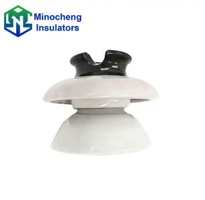
Pin insulators are the earliest developed type of overhead insulators, specifically designed to be mounted on a pin that is fixed to the cross-arm of a utility pole. They provide a secure mechanical support for the conductor while ensuring electrical isolation between the live line and the grounded support structure.
In the realm of electrical power distribution, the Pin Insulator remains a primary choice for medium voltage applications. These components are characterized by their "petticoat" or "shed" design, which increases the creepage distance—the shortest path along the surface of the insulator between the energized part and the grounded part. By extending this path, the insulator significantly reduces the risk of leakage current even during heavy rainfall or high humidity.
Historically, these insulators were made exclusively of porcelain, but modern advancements have introduced silicone rubber and toughened glass variants. Their simple yet effective design allows for easy mounting. A galvanized steel pin is inserted into a threaded hole at the base of the insulator, which is then bolted to the cross-arm. This rigid mounting system makes them ideal for straight-line distribution where the conductor tension is relatively low compared to transmission lines.
When selecting components for a project, it is vital to source high-quality hardware. For instance, you might consider the high-voltage distribution pin insulator to ensure long-term stability and electrical performance in demanding environmental conditions. These units are engineered to meet international standards like IEC and ANSI, providing the necessary safety margins for public utility grids.
The structure of a pin insulator is defined by its vertically mounted, umbrella-like layers called sheds or petticoats, which are designed to keep the inner parts dry. The core body features a groove at the top for holding the conductor and a threaded hole at the bottom for pin attachment.
The mechanical integrity of a Pin Insulator depends on its physical architecture. The top of the insulator has a "conductor groove" where the power line is placed and secured with binding wire. Below this, the insulator body expands into one or more sheds. These sheds are strategically angled to allow rainwater to drip off without wetting the entire surface of the insulator. This prevents the formation of a continuous water film, which could lead to a catastrophic electrical flashover.
Internally, the insulator contains a thimble or a threaded area. In porcelain models, this thimble is often lead-lined or cemented to prevent the steel pin from exerting uneven mechanical stress on the brittle ceramic, which could cause cracking due to thermal expansion. The overall height and diameter of the sheds are determined by the voltage rating; higher voltages require more sheds to provide a longer leakage path.
Standard structures often follow specific ANSI classes. For example, the ANSI standard porcelain pin insulator provides a standardized structural template that ensures compatibility with various utility pole hardware. The smooth, glazed surface of the porcelain helps in self-cleaning, as dust and pollutants are easily washed away by rain, maintaining the structural and electrical health of the unit.
The working principle of a pin insulator is based on providing a high-resistance path to current flow and maximizing the creepage distance through its physical shape. By forcing any potential leakage current to travel over the intricate surfaces of the sheds, it prevents electrical discharge to the ground.
When a high-voltage conductor is placed in the top groove of a Pin Insulator, the potential difference between the wire and the grounded pin is immense. The air surrounding the insulator acts as a primary dielectric, but the insulator itself must withstand the voltage stress. The "petticoats" increase the surface area between the two points. Because electricity seeks the path of least resistance, a longer surface path (creepage distance) makes it difficult for current to "creep" across the surface to the pin.
In dry conditions, the air provides excellent insulation. However, during rain or fog, the surface can become conductive. The downward-sloping sheds ensure that at least a portion of the insulator remains dry, breaking the continuity of the conductive moisture film. This is known as "dry arcing distance." The insulator must be designed so that even if the outer sheds are wet, the internal sections remain dry enough to prevent a short circuit.
Furthermore, the dielectric strength of the material—whether it be porcelain or polymer—is critical. It must resist "puncture," where the electricity literally burns a hole through the solid material. Most pin insulators are designed such that the "flashover voltage" (the voltage at which air breaks down and an arc forms over the surface) is much lower than the "puncture voltage," ensuring that if a surge occurs, the arc stays on the outside rather than destroying the insulator internally.
The materials used in pin insulators are primarily porcelain, toughened glass, or polymer composites, each selected for its high dielectric strength and mechanical durability. Porcelain remains the industry standard due to its excellent resistance to UV radiation, chemicals, and extreme temperatures.
Porcelain insulators are made from a mixture of plastic kaolin, feldspar, and quartz. This mixture is fired at high temperatures to create a dense, non-porous material. A brown or gray glaze is applied to the surface to prevent moisture absorption and to facilitate the shedding of dirt. The mechanical strength of porcelain is high in compression, which is perfect for supporting the weight of heavy conductors on a Pin Insulator.
Polymer or composite insulators are a more modern alternative. These consist of a fiberglass core rod for mechanical strength, covered with a silicone rubber housing. The primary advantage of polymer is its "hydrophobicity"—it naturally repels water. Water on the surface forms individual beads rather than a film, which significantly improves performance in coastal or polluted areas where salt and dust buildup is common.
| Material Type | Advantages | Disadvantages |
| Porcelain | High thermal stability, long lifespan (30+ years), cost-effective. | Brittle, heavy, prone to damage from vandalism (rocks/bullets). |
| Toughened Glass | Easy inspection (visible cracks), high mechanical strength. | Sensitive to moisture in certain climates, heavier than polymer. |
| Polymer/Silicone | Lightweight, hydrophobic, excellent in polluted areas. | Lower UV resistance than porcelain, shorter lifespan, prone to bird pecking. |
For many grid operators, the durable porcelain pin insulator is preferred for its proven track record in diverse climates. Its ability to withstand thermal cycling without losing dielectric properties makes it a reliable investment for long-term infrastructure.
Pin insulators are predominantly used in electrical distribution systems with voltage levels up to 33kV. They are the standard choice for straight-run utility poles, rural electrification, and urban power distribution where the physical layout allows for rigid mounting.
The primary application of the Pin Insulator is in intermediate support on utility poles. They are not typically used for dead-ends or sharp corners where the conductor tension is very high; in those cases, suspension or strain insulators are preferred. However, for the majority of a power line's length, pin insulators provide a cost-effective and easy-to-install solution. They are widely used in both single-phase and three-phase distribution networks.
In industrial parks and residential neighborhoods, these insulators keep the 11kV or 33kV lines safely elevated. Because they are compact, they allow for a cleaner aesthetic on utility poles compared to large suspension strings. They are also frequently used in substations to support busbars or as part of disconnect switches where rigid insulation is required.
Specific environmental conditions often dictate the choice of insulator. For instance, in areas with high industrial pollution, a specialized 33kV pin insulator with extra-large sheds might be used to provide additional creepage distance. This ensures that the power supply remains uninterrupted even when the air is thick with conductive particles or sea salt.
Rural Electrification: Connecting remote villages to the main grid.
Urban Distribution: Managing power flow along city streets.
Primary Feeders: Carrying power from substations to local transformers.
Temporary Power Lines: Used in construction or emergency grid repairs.
Proper installation of a pin insulator requires precise alignment of the galvanized steel pin and careful binding of the conductor to the top groove. The pin must be securely bolted to the cross-arm, ensuring a vertical orientation that allows the sheds to shed water effectively.
The first step in installation is selecting the correct pin for the insulator. The pin is typically made of forged steel and must be galvanized to prevent rust. The threaded end of the pin is coated with a small amount of lubricant or specialized compound before being screwed into the Pin Insulator. It is crucial not to over-tighten, as the mechanical stress can lead to hairline fractures in the porcelain, which will eventually cause electrical failure.
Once the insulator-pin assembly is mounted on the cross-arm, the conductor is lifted into the top groove. It is then secured using "tie-wires" or "binding wires." These wires must be made of the same material as the conductor (usually aluminum) to prevent galvanic corrosion. The tie must be tight enough to prevent the conductor from slipping but flexible enough to allow for slight movements caused by wind or temperature-induced expansion and contraction.
Safety during installation is paramount. Linemen must ensure that the insulators are clean and free of cracks before they are sent up the pole. Even a small chip in the glaze can collect moisture and lead to a flashover. Furthermore, the cross-arm must be level; a tilted Pin Insulator will not shed water correctly, significantly reducing its effective insulation rating during a storm.
Maintenance of pin insulators involves regular visual inspections for cracks, cleaning of surface contaminants, and testing for electrical leakage. Proper care extends the life of the insulator and prevents unplanned power outages caused by flashovers or mechanical failure.
Over time, insulators can accumulate layers of dust, salt, or industrial pollutants. In dry weather, this is not a problem, but light rain or fog can turn this dust into a conductive paste. Regular cleaning, often performed via "live-line washing" with high-pressure deionized water, is necessary in high-pollution zones. For Pin Insulator units, it is important to inspect the area where the pin enters the body, as this is a common point for moisture ingress and corrosion.
Visual inspections should look for "tracking"—carbonized paths on the surface of the insulator caused by small electrical arcs. If tracking is found, the insulator must be replaced immediately. Thermal imaging cameras are also used to detect "hot spots," which indicate internal leakage or a puncture. In porcelain models, look for "crazing," which are tiny cracks in the glaze that can eventually lead to deeper structural issues.
In conclusion, the Pin Insulator is a foundational element of modern society's power grid. By combining traditional materials with engineered designs, these components ensure that electricity reaches homes and businesses safely and efficiently. Whether you are installing a new line or maintaining an existing one, choosing high-quality materials and following strict installation protocols is the only way to ensure a resilient electrical future. Regular monitoring and proactive replacement are the keys to a zero-failure distribution network.


