


Views: 0 Author: Site Editor Publish Time: 2026-05-15 Origin: Site


A post insulator is distinguished from a pin insulator primarily by its rigid mounting configuration and superior cantilever strength, making it the preferred choice for higher voltage applications and complex mechanical loads.
Understanding these hardware differences is essential for procurement officers and grid engineers aiming to optimize their infrastructure. Whether you are maintaining a legacy network or designing a new transmission route, recognizing how different support components handle electrical stress and physical tension will directly impact your grid’s uptime. This article explores the technical nuances between these two critical components, providing a comprehensive guide to their applications and the challenges they face in the field.
| Section | Summary |
| Factors influencing material selection for post insulator | Examines how environmental conditions and mechanical loads dictate the choice of materials like porcelain or composite. |
| Advantages and disadvantages of using post insulator in transmission lines | Details the benefits of high load-bearing capacity versus potential vulnerabilities in specific mounting scenarios. |
| Community forums and engagement for post insulators | Discusses the importance of industry knowledge sharing and collective troubleshooting for technical optimization. |
| Challenges and issues facing post insulators | Highlights the technical difficulties of surface contamination and structural stress in extreme weather. |
| Differences between a pin insulator and a post insulator | Contrasts design, installation flexibility, and the primary electrical functions of these two distinct support types. |
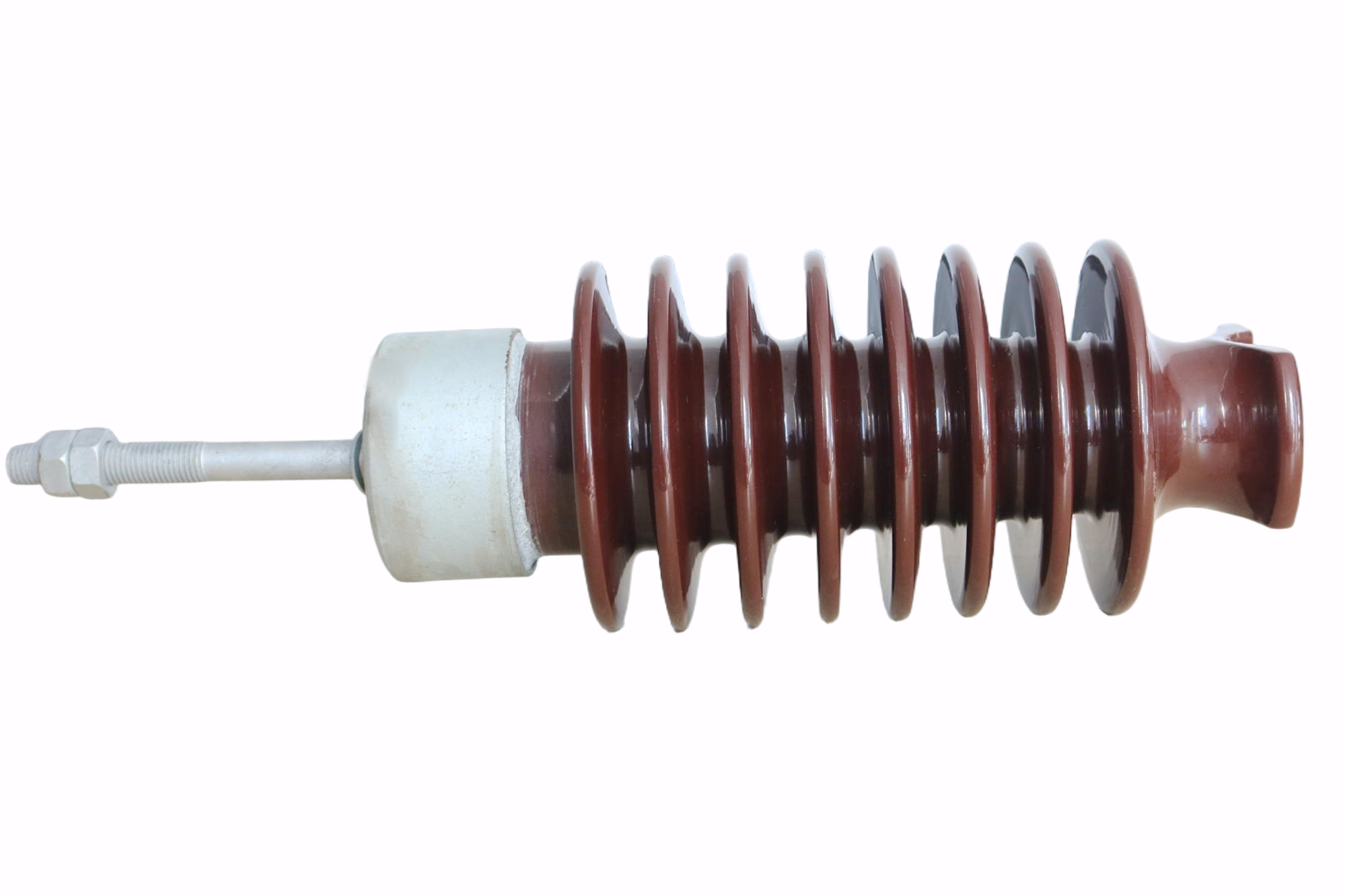
Material selection for a post insulator is primarily driven by the need to balance dielectric strength, resistance to environmental pollutants, and mechanical durability against site-specific stresses.
When selecting a high-performance insulator, engineers must first assess the environmental profile of the installation site. In coastal or heavily industrialized regions, the material must possess superior anti-fouling properties to prevent tracking and flashover. Porcelain remains a standard due to its high dielectric strength and chemical inertness, while composite materials are often chosen for their lighter weight and enhanced hydrophobic surfaces, which help manage moisture in humid climates.
Mechanical load requirements serve as another significant factor in material selection. Because a post insulator is frequently subjected to high bending moments and cantilever forces, the material must offer a high modulus of elasticity and tensile strength. Design teams often rely on the integration of high-alumina ceramic cores or fiberglass-reinforced epoxy rods to ensure the hardware can withstand heavy wind loads, ice accumulation, and the weight of high-tension conductors without suffering from fatigue or brittleness over time.
Finally, long-term maintenance costs and life-cycle assessments influence the procurement process. Projects with limited access for maintenance teams often prioritize materials that provide high structural stability with minimal degradation, effectively reducing the frequency of site visits. Understanding the core properties of these materials is as critical as evaluating the electrical specifications, ensuring that the high-performance support component chosen for the grid is capable of performing reliably for decades.
The primary advantage of a post insulator in transmission lines is its robust cantilever strength, which allows it to handle significant conductor tension, although its rigidity can occasionally lead to issues under extreme vibrational stress.
One of the most notable benefits is the structural stability provided by the rigid mounting. Unlike suspension-style hardware, this design keeps the conductor in a fixed position, which is vital for maintaining required clearances in congested utility corridors. For engineers designing medium-to-high voltage lines, these components offer a compact solution that excels in resisting both horizontal and vertical loads, often simplifying the cross-arm design and reducing the physical footprint of the transmission pole.
However, there are disadvantages to consider. The inherent stiffness of the construction means that during severe weather events or seismic activity, the energy transfer to the supporting structure can be substantial. In some cases, this leads to the need for additional damping mechanisms to protect both the insulator and the pole from fatigue. While many utilities prefer the reliability of these units, they are also sensitive to incorrect installation; if not properly aligned, the stress distribution can be uneven, leading to localized mechanical failures.
When comparing these options, it is helpful to contrast them with simpler pin-style insulation products that might be used in lower-voltage distribution. While a pin insulator is excellent for straightforward, low-load distribution lines, the post variant provides the extra mechanical safety factor required for complex transmission setups. Evaluating the trade-offs between load capacity and vibration sensitivity ensures that the chosen hardware aligns with the specific geographical and operational requirements of the transmission project.
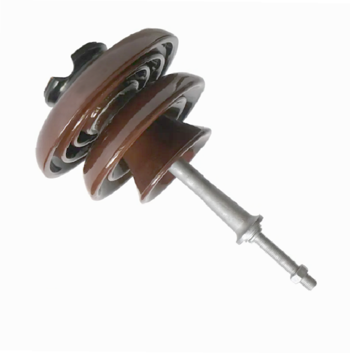
Community engagement and industry forums serve as vital platforms for engineers to share empirical data and troubleshooting strategies, ultimately improving the reliability of the post insulator across global networks.
Modern grid management relies heavily on the collective intelligence of the electrical engineering community. Because field conditions vary wildly—from the salt-heavy air of maritime regions to the extreme temperature swings of inland deserts—manufacturers and utilities benefit from shared experiences. Forums and technical workshops allow professionals to discuss, for example, how specific coatings or shapes perform under unique contamination scenarios, helping the industry develop better standards for long-term deployment.
Participation in these communities also aids in the early identification of common hardware failure modes. When engineers report persistent issues with specific configurations or aging patterns, manufacturers can accelerate the development of more durable solutions. This feedback loop is essential, as it translates theoretical performance data from laboratory tests into real-world, actionable insights that help grid operators maintain higher uptime levels.
Furthermore, these platforms provide guidance for selecting the right hardware for specific maintenance or upgrade tasks. Professionals often turn to community consensus when deciding whether to stick with legacy porcelain designs or pivot toward modern composite materials. By leveraging these shared resources, utilities ensure that their procurement teams are equipped with the latest technical knowledge, mirroring the high standard of guidance typically provided by specialized suppliers of durable insulation hardware.
The most significant challenges for a post insulator involve managing surface degradation due to environmental contamination and mitigating structural stresses during extreme weather events.
In many regions, industrial pollution, road salt, and agricultural dust accumulate on the surface of the insulator. Over time, these pollutants interact with moisture to form a conductive layer that significantly increases the risk of flashover. Engineers must often perform regular inspections and cleaning cycles to maintain the integrity of the insulation surface, especially when the creepage distance has been compromised by thick layers of grime. Designing hardware with advanced anti-fouling glaze or shed profiles is the standard approach to slowing this degradation.
Structural stress presents another layer of difficulty. In areas prone to high-speed winds or heavy ice loading, the cantilever strength of the component is pushed to its limit. If the hardware is not matched perfectly to the mechanical load, microscopic cracks can develop, particularly at the junction where the insulator meets the steel base. These small defects can lead to premature failure if left unaddressed, highlighting the need for rigorous quality control during the manufacturing process and precise installation in the field.
Additionally, internal aging of the insulator—such as the cement hydration in porcelain types—can cause expansion over decades, leading to internal stress. This is particularly problematic in areas with extreme temperature cycles. By closely monitoring site-specific conditions and selecting hardware with known durability records, grid managers can effectively combat these challenges, ensuring the long-term safety and operational stability of the electrical network.
The primary difference between a pin insulator and a post insulator lies in their mechanical mounting: pin types are designed to support conductors on top of the insulator pin, while post types feature a more rigid base attachment designed to handle significantly higher cantilever forces.
A pin-type insulator is generally suited for lower voltage distribution systems where the mechanical loads are relatively modest. The conductor is typically tied to the top of the insulator, allowing for a simpler, more cost-effective installation. This configuration is widely used for distribution lines where minimizing costs while maintaining standard insulation performance is the top priority. They are effective for the vertical loads typical of standard distribution setups but are rarely utilized where heavy tension or high-angle pulling is required.
In contrast, the post insulator is engineered for heavy-duty roles. Its base is designed to be bolted securely to the cross-arm, providing a stable support system that acts much like a structural column. This enables the device to sustain high bending and cantilever forces, which makes it ideal for transmission lines or substations where the conductor tension is significant. Because of its structural design, it can be mounted in various positions, including horizontal or vertical configurations, offering much more flexibility than the pin type.
When choosing between these two, consider the following structural and operational differences:
Load capacity: Post designs excel in high-tension environments, whereas pin types are optimized for lighter vertical loads.
Mounting configuration: Post units offer versatile mounting options, while pin units are generally limited to vertical top-tie applications.
Voltage applicability: Post units are commonly used in medium to extra-high voltage systems due to their larger size and structural robustness, while pin units are standard in lower voltage distribution.
Ultimately, the choice hinges on the mechanical requirements of the line. For basic distribution, the efficiency of a well-made pin unit is unmatched, but for infrastructure requiring high mechanical safety factors, the structural integrity of the post unit is indispensable.
Choosing between a pin and a post insulator is a foundational decision in electrical infrastructure management. While pin insulators offer an efficient solution for standard, lower-voltage distribution, the structural, high-cantilever capacity of the post insulator makes it a critical component for demanding transmission lines and complex grid architectures. By understanding the mechanical limitations and environmental challenges associated with each, engineers can better select the hardware that ensures the long-term reliability and performance of their systems.


